Transfer Carriages
Space-saving solutions for maximum efficiency.
Optimal space utilization with precise transverse movement
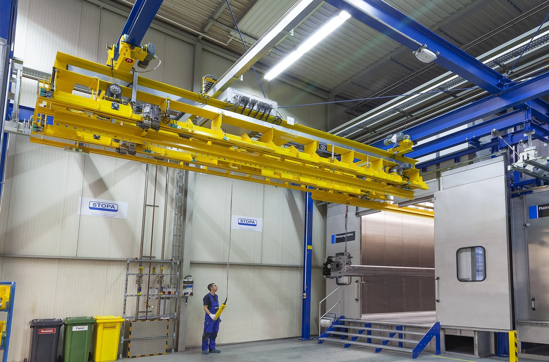
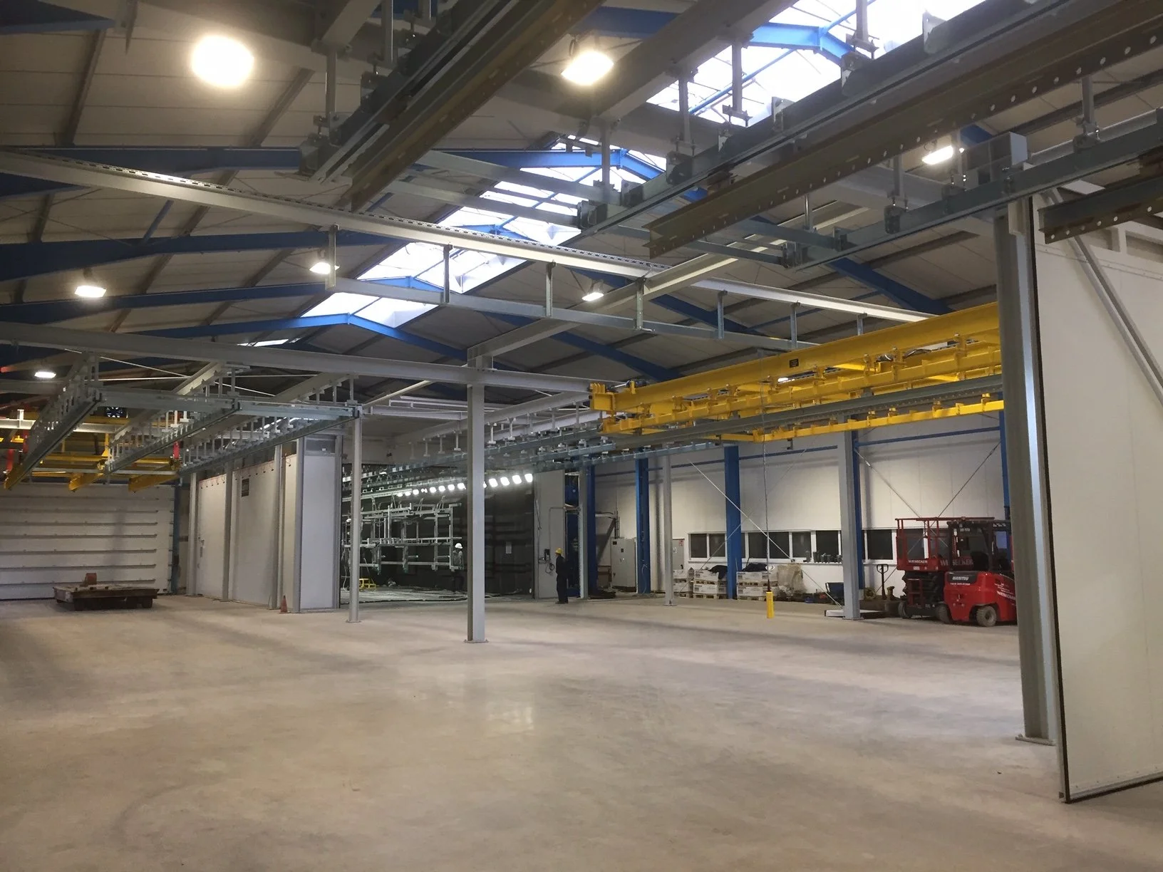
Traverse systems connect parallel tracks and stations within confined spaces. They reliably transport loads transversely across the production or storage area, either manually or fully automated. These systems offer scalable load capacities, modular expandability, low maintenance, and enhanced safety, particularly in restricted facility layouts.
Technical Specifications:
Load Capacity: 500–16,000 kg
Operation: Manual or Automatic
Easily Expandable
Low Maintenance
Ideal for production and storage areas with multiple connection points and limited space.
Optional:
Bends
Switches
Turntables
Lift-and-Lower Stations
Transfers (semi-automated)
Rotations (semi-automated)
System Overview
Eine Verschiebebrückenanlage ist ein fördertechnisches System, das zum horizontalen Transport von Fahrzeugen, Lastträgern oder Fördergütern zwischen mehreren parallel angeordneten Strecken, Arbeitsstationen oder Förderbereichen eingesetzt wird.
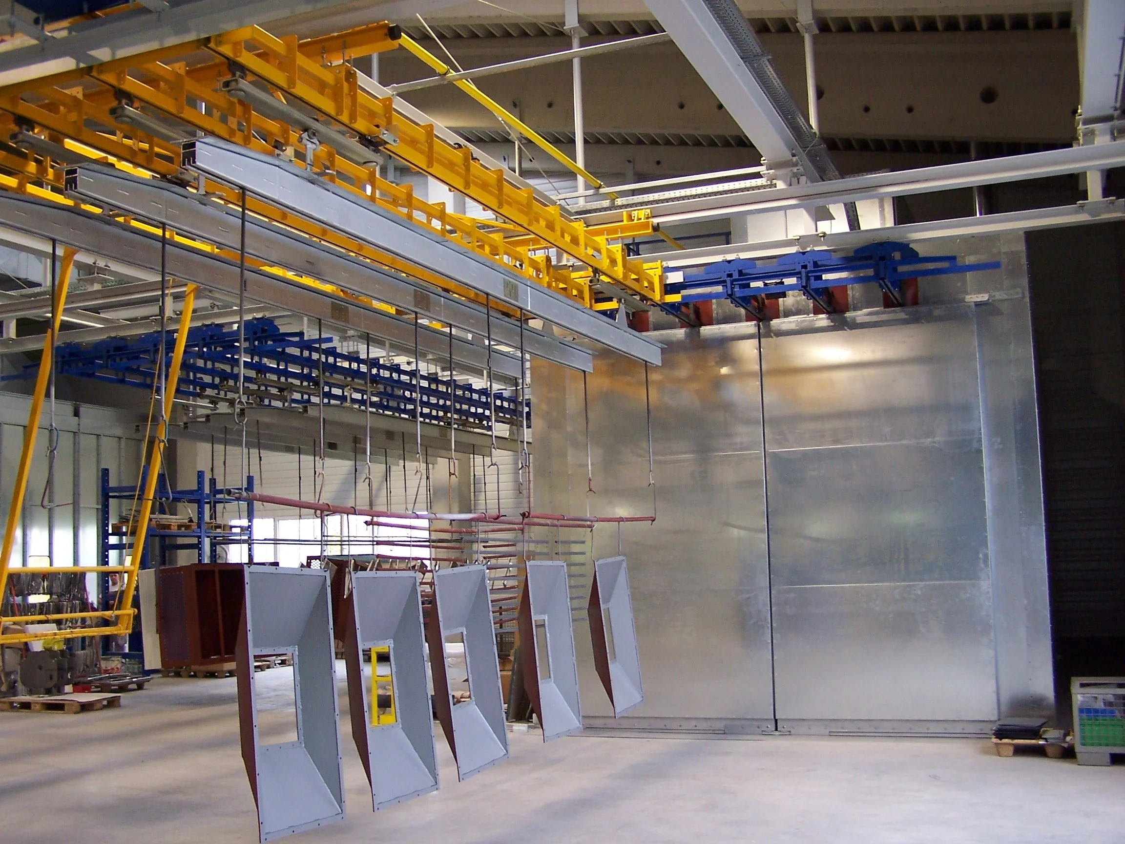
- Overhead Conveyor Systems
- Assembly Conveyors
- Storage and Production Systems
- Transfer Stations
System Components
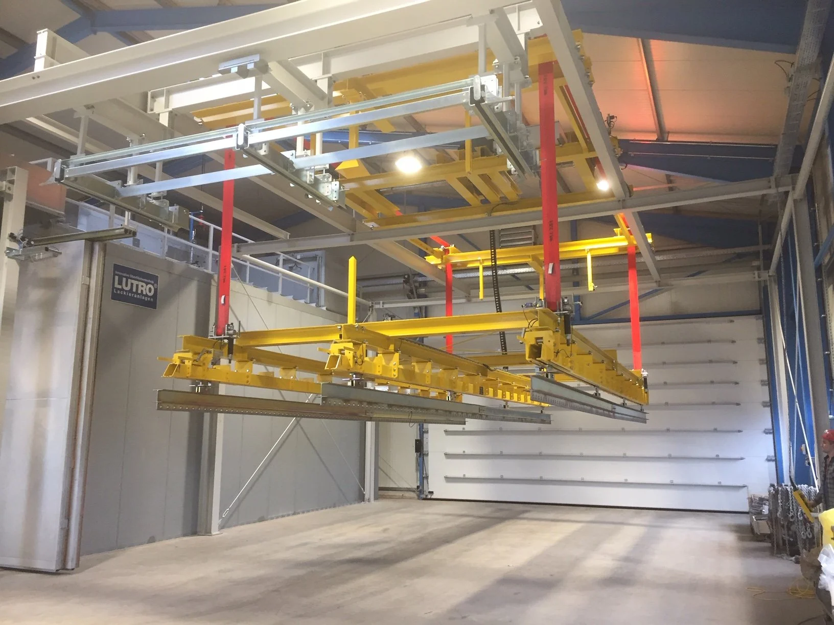
- Traversing Bridge Unit (Shuttle / Transfer Cart)
- Running Gear with Wheels or Rail Guides
- Drive System, e.g., Electric Drive
- Limit and Position Sensor Technology
- Safety and Control Technology
Operating Principle of the Transfer Bridge
The transfer bridge is designed to move load carriers or vehicles between multiple tracks or rails, position them at defined transfer points, and execute controlled transfers to subsequent conveyor systems.
- Traversing to the desired target position
- Precise positioning at the transfer point
- Coupling or transfer of the conveyed goods
System Principle
The bridge traverses perpendicular to the main conveying direction, precisely positions itself at the desired transfer point, and facilitates the secure transfer to the subsequent system.
Automatic Operation
In automatic mode, the transfer carriage executes all movements autonomously, as dictated by the system control.
- Approaching target positions
- Locking and unlocking of transfer points
- Synchronization with the main conveying system
- Monitored transfer of vehicles or load carriers
Manual Operation
Manual operation is primarily used for service work, fault rectification, and manual positioning.
- Emergency Stop
- Motor Protection
- Limit Switches
- Safety Interlocks
Movements must only be performed by trained personnel.
Safety Functions
The transfer carriage system is equipped with multiple safety-relevant components.
- End-position switches for safely limiting travel movement
- Positioning sensors for precise alignment
- Standstill monitoring at transfer points
- Mechanical stops as emergency end positions
- Emergency stop devices along the operating side
- all safety circuits are closed
- no personnel are detected within the hazardous area
- all interlocks are released
Initiating the Transfer Carriage
- Power on the control system.
- Select operating mode: Automatic or Manual.
- Verify Safety Interlocks
- Select Target Position or Transfer Point
- Issue Start Command
Travel Between Positions
- Travel at Constant or Adjustable Speed Along the Guide
- Controlled Deceleration at the End Position
- Automatic Locking at Transfer Points
Transfer to Other Systems
At the end position, the carriage couples or unlatches:
- Mechanically, e.g., via stops or locking pins
- Electrically, e.g., via signal interlocks
The subsequent process is then enabled by the control system, e.g., for vehicle entry.
Special Operating Instructions
- The transfer carriage must not be accessed while it is capable of movement.
- Movements may only be initiated when no personnel are within the travel path.
- In the event of a malfunction, the system must be immediately shut down and the cause of the fault investigated.
- In manual mode, movements must only be executed for short durations and under controlled conditions.
Maintenance and Inspection
Regular inspections ensure safe and reliable operation.
- Functional check of limit switches and sensors
- Inspection of travel paths and rails
- Verification of mechanical stops
- Lubrication of running gear components, if required
- Visual inspection of the electrical system
Technical Note
Maintenance work must only be performed by qualified technical personnel.
System Overview
A traverse car system is a material handling system designed for the horizontal transport of vehicles, load carriers, or conveyed goods between multiple parallel tracks, workstations, or conveying areas.
- Overhead Conveyor Systems
- Assembly Conveyors
- Storage and Production Systems
- Transfer Stations
System Components
- Traversable bridge unit
- Running Gear with Wheels or Rail Guides
- Drive system
- Limit and Position Sensor Technology
- Safety and Control Technology
Operating Principle
- Transfer between multiple tracks or rails
- Entry into defined transfer positions
- Controlled transfer to subsequent conveying equipment
- Precise positioning at the destination
System Principle
- Transverse movement relative to the main conveying direction
- Precise positioning
- Coupling or transfer of the conveyed goods
Automatic Operation
- Approaching target positions
- Locking and unlocking of transfer points
- Synchronization with the main conveying system
- Monitored transfer of vehicles or load carriers
- Software-based monitoring active
Manual Operation
- For service operations
- For fault rectification
- For manual positioning
- Active hardware safety features: emergency stop, motor protection, limit switches, interlocks
Safety Functions
- Limit switches
- Positioning sensors
- Standstill monitoring at transfer points
- Mechanical stops as emergency end positions
- Emergency stop devices along the operating side
- All safety circuits closed
- No personnel in the danger zone
- All interlocks released
Initiating the Transfer Carriage
- Power on the control system.
- Select Operating Mode
- Verify Safety Interlocks
- Select target position
- Issue Start Command
Travel Between Positions
- Travel along the guide
- Controlled Deceleration at the End Position
- Automatic interlocking at transfer points
Transfer to Other Systems
- Mechanical coupling or release
- Electrical signal interlocking
- Enabling of the downstream process by the control system
Special Operating Instructions
- Do not enter the transfer carriage while it is capable of movement
- Only initiate movements when no personnel are within the travel path
- In the event of a fault, immediately shut down the system and investigate the cause
- In manual mode, only operate briefly and under controlled conditions
Maintenance and Inspection
- Functional check of limit switches and sensors
- Inspection of travel paths and rails
- Verification of mechanical stops
- Lubrication of the running gear components
- Visual inspection of the electrical system
Maintenance work must only be performed by qualified technical personnel.
-
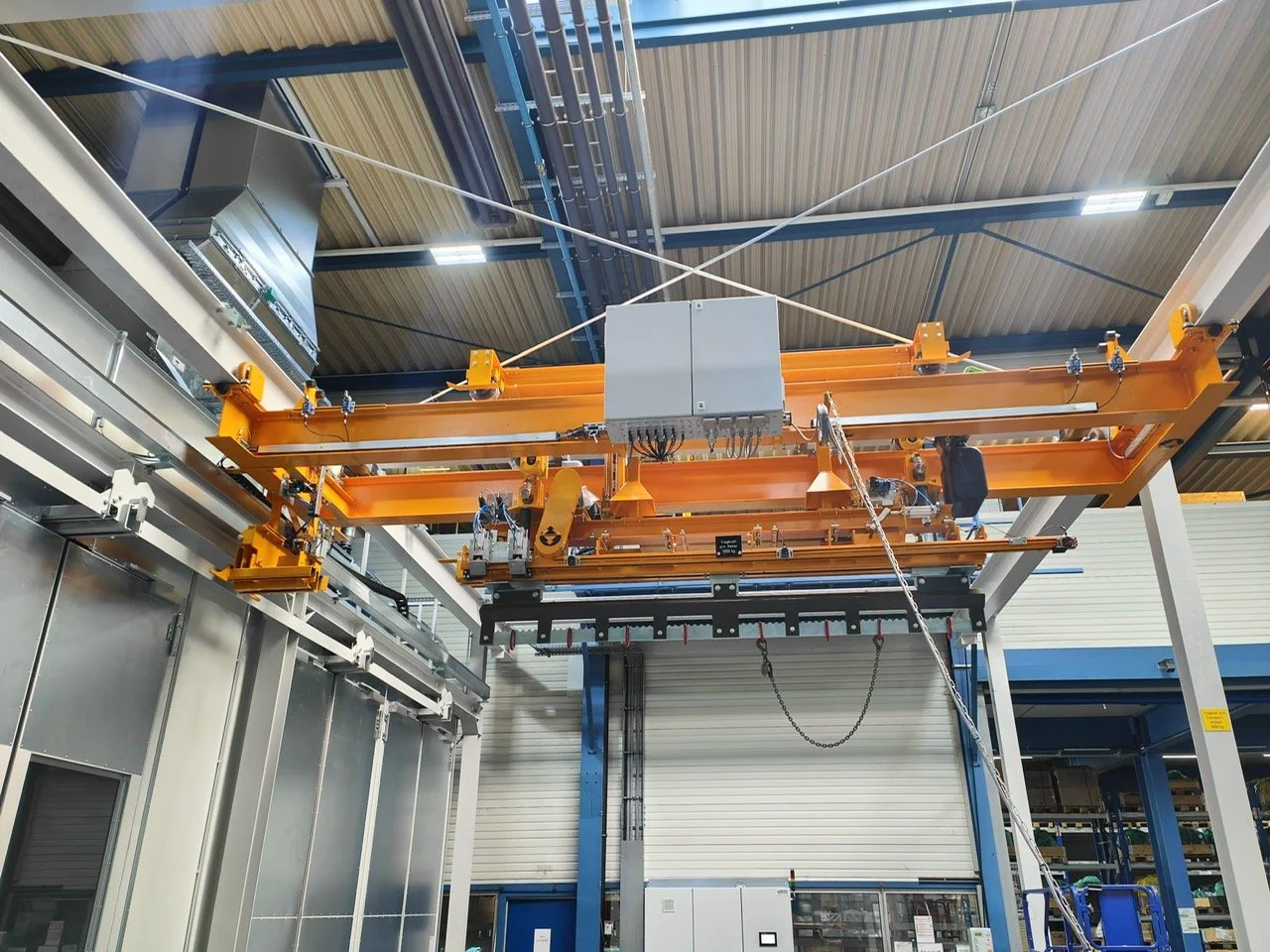
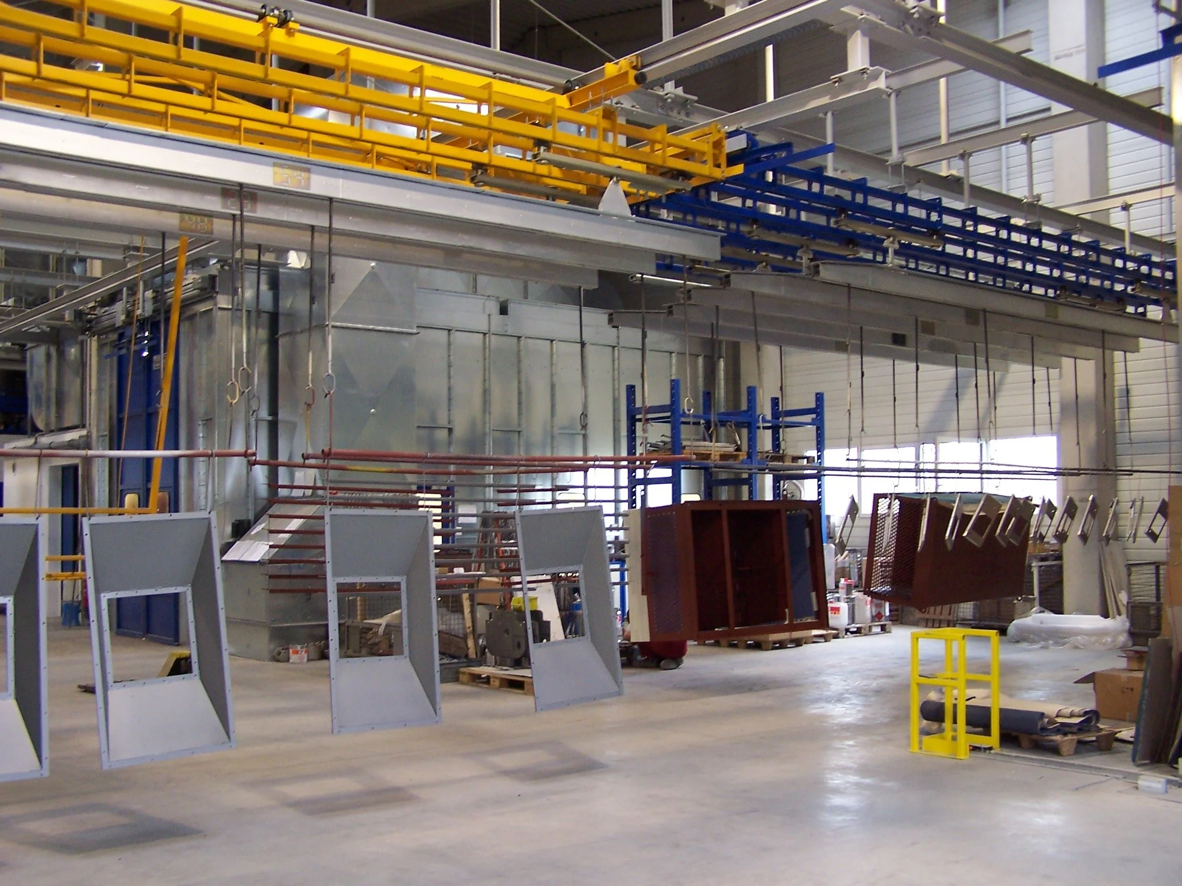
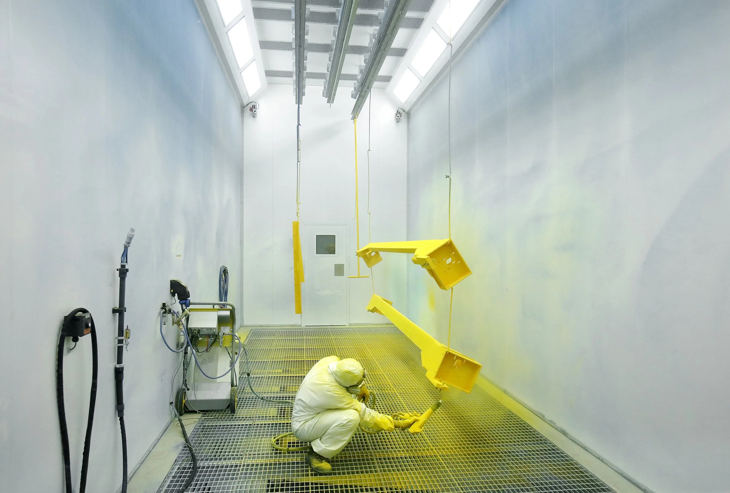
![Transfer Carriage H150 Cabin]()
Transfer Carriage H150 Cabin
-
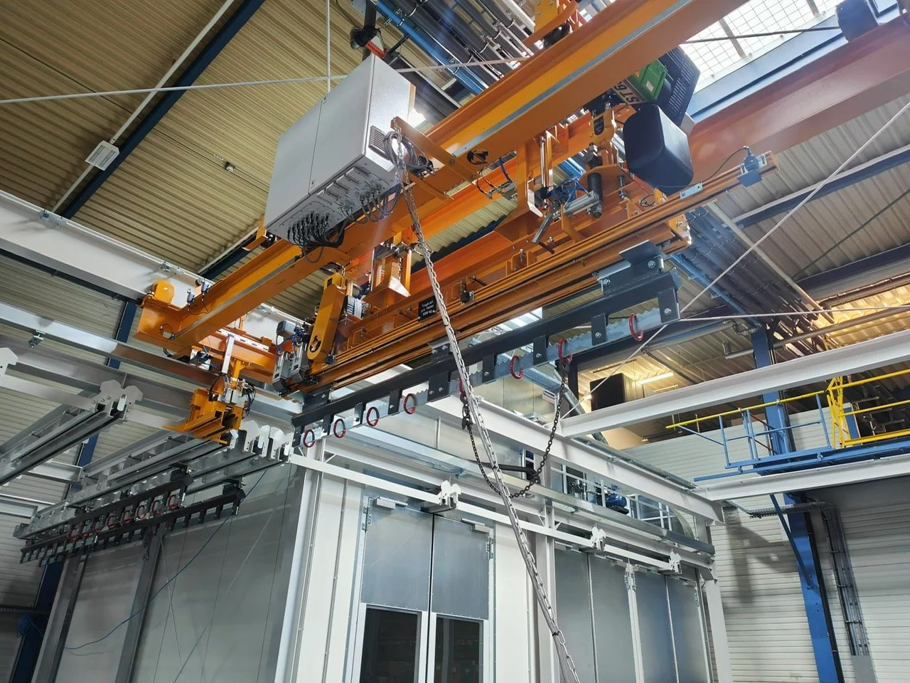
![Transfer Carriage H150 Storage]()
Transfer Carriage H150 Storage
-
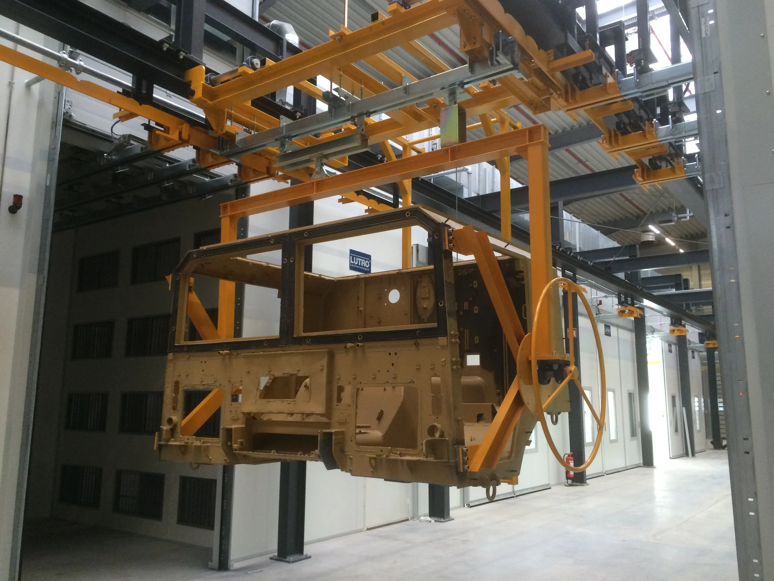
![Transfer Carriage H150 Workpiece]()
Transfer Carriage H150 Workpiece
-
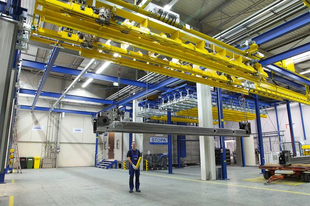
![Transfer Carriage H150 Lift-Lower Station]()
Transfer Carriage H150 Lift-Lower Station
-
![Transfer Carriage H150 Lift-Lower Station]()
Transfer Carriage H150 Lift-Lower Station
-
![Transfer Carriage H150 Conveyor Path]()
Transfer Carriage H150 Conveyor Path
-
![Transfer Carriage H150 Lift-Lower Station]()
Transfer Carriage H150 Lift-Lower Station
-
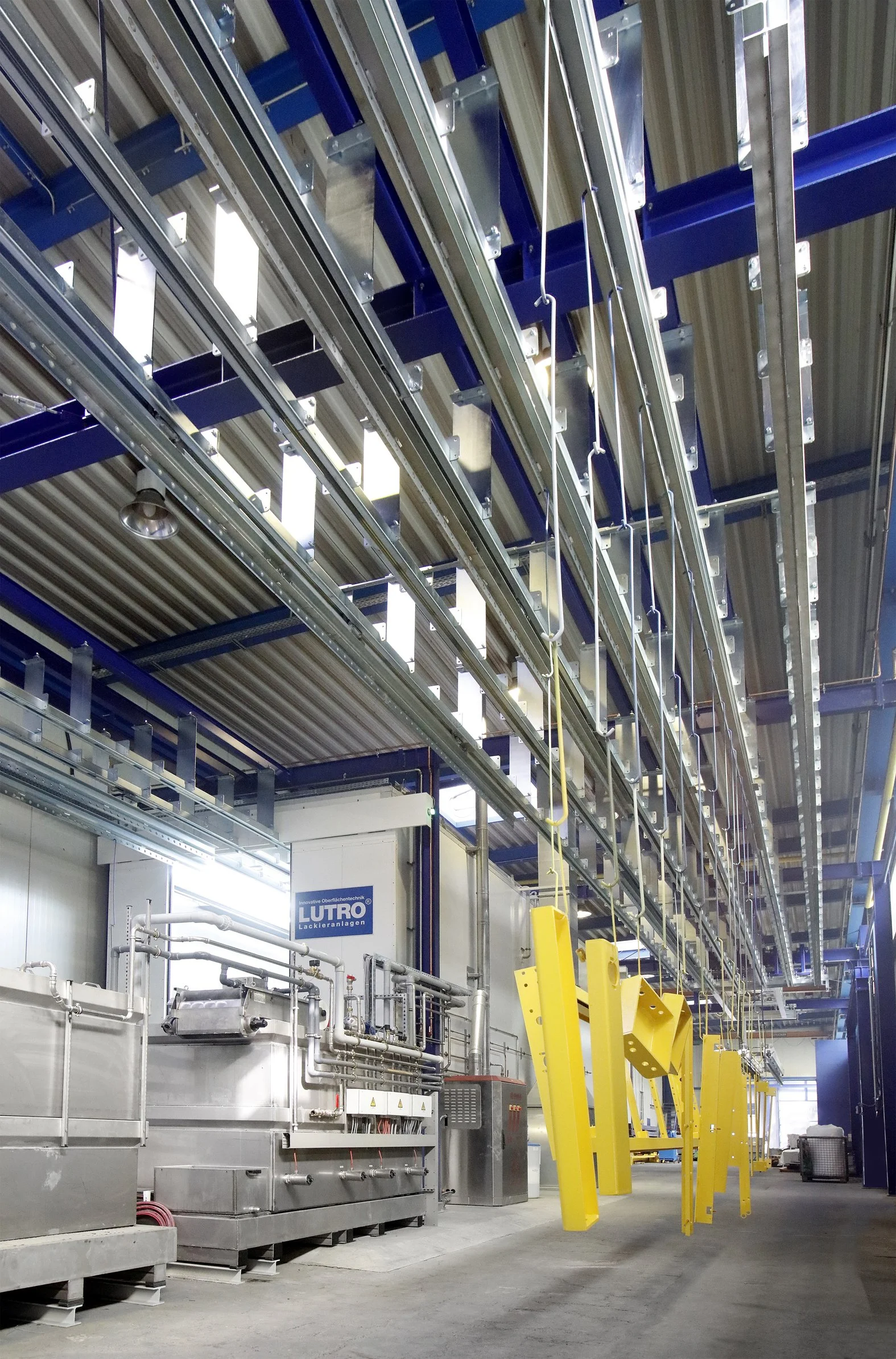
![Transfer Carriage F70 Dryer]()
Transfer Carriage F70 Dryer
-
![Transfer Carriage F70 Workpieces]()
Transfer Carriage F70 Workpieces
-
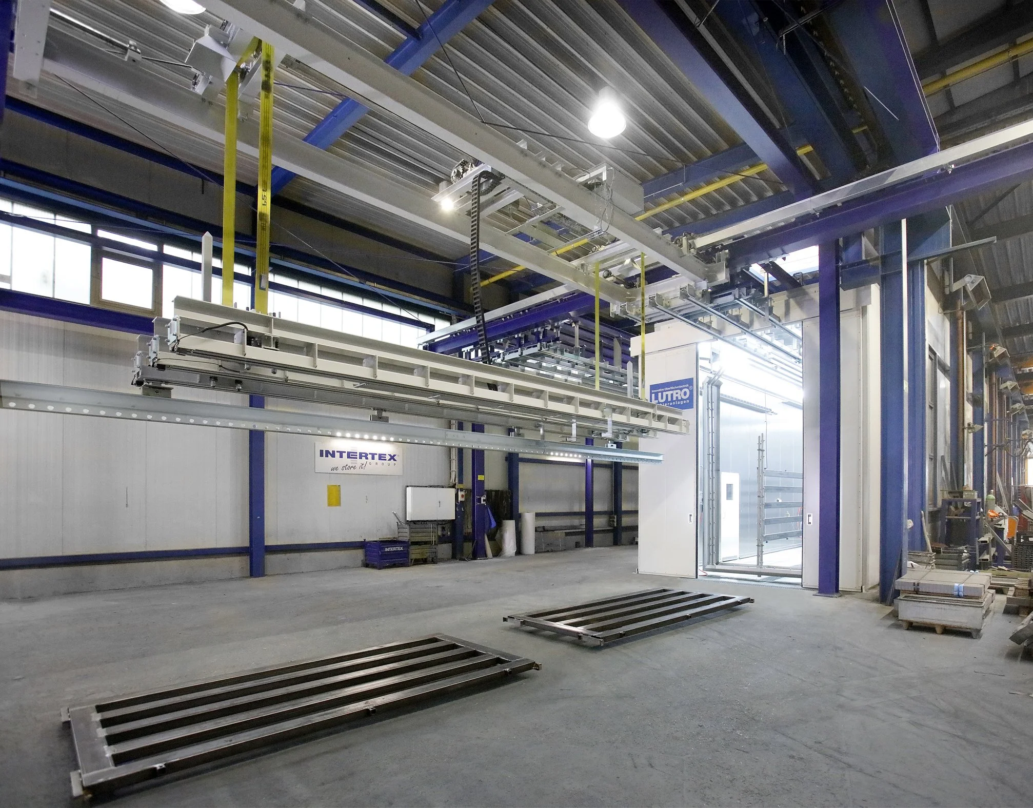
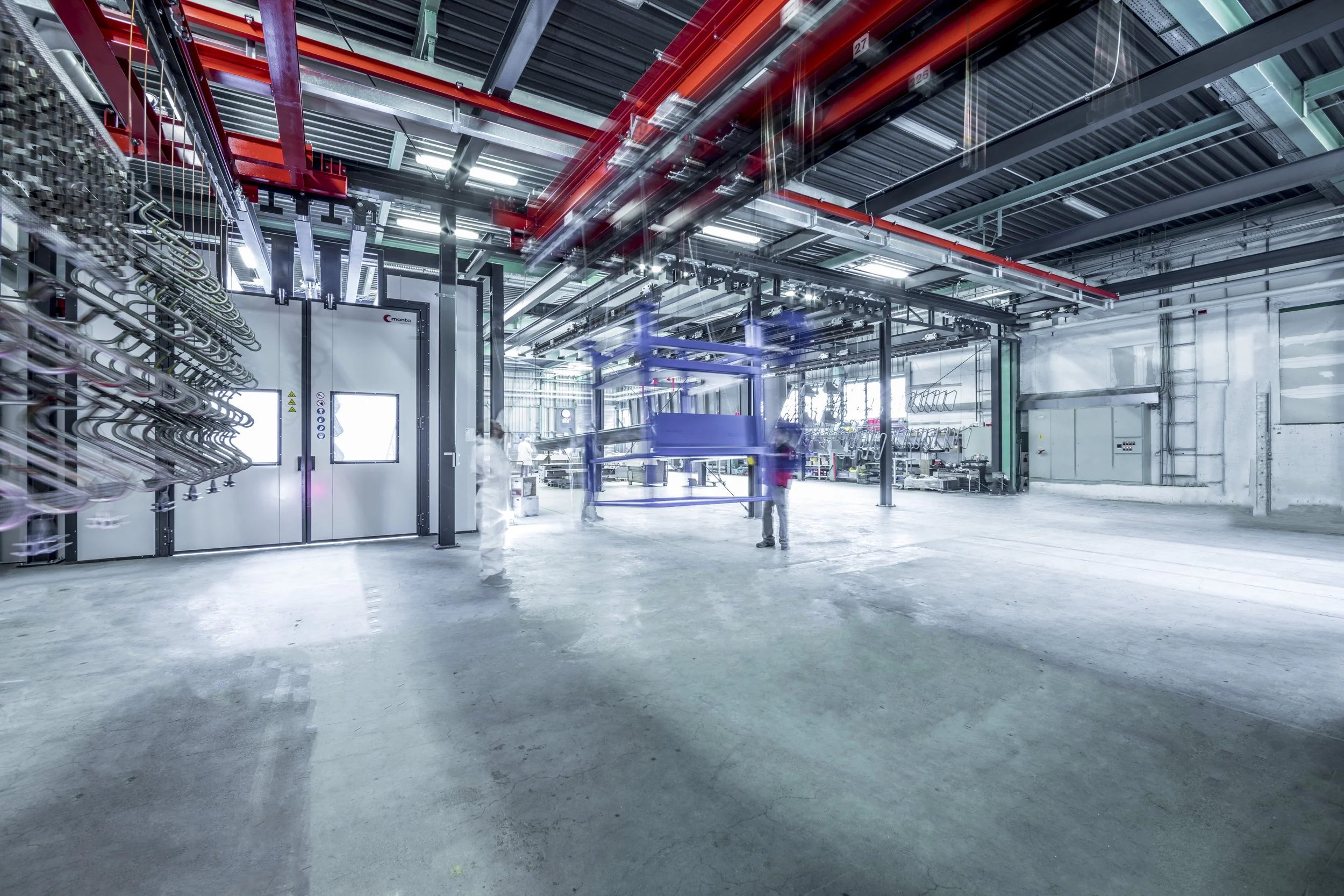
![Transfer Carriage H100 Conveyor Path]()
Transfer Carriage H100 Conveyor Path
-
![Transfer Carriage H100 Lift-Lower Station]()
Transfer Carriage H100 Lift-Lower Station
-
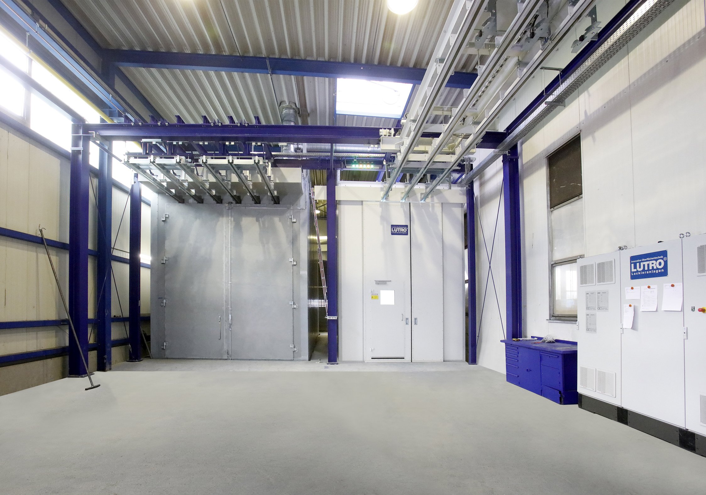
![Transfer Carriage H100 Dryer Cabin]()
Transfer Carriage H100 Dryer Cabin
-
![Transfer Carriage H100 Powder Booth]()
Transfer Carriage H100 Powder Booth
-
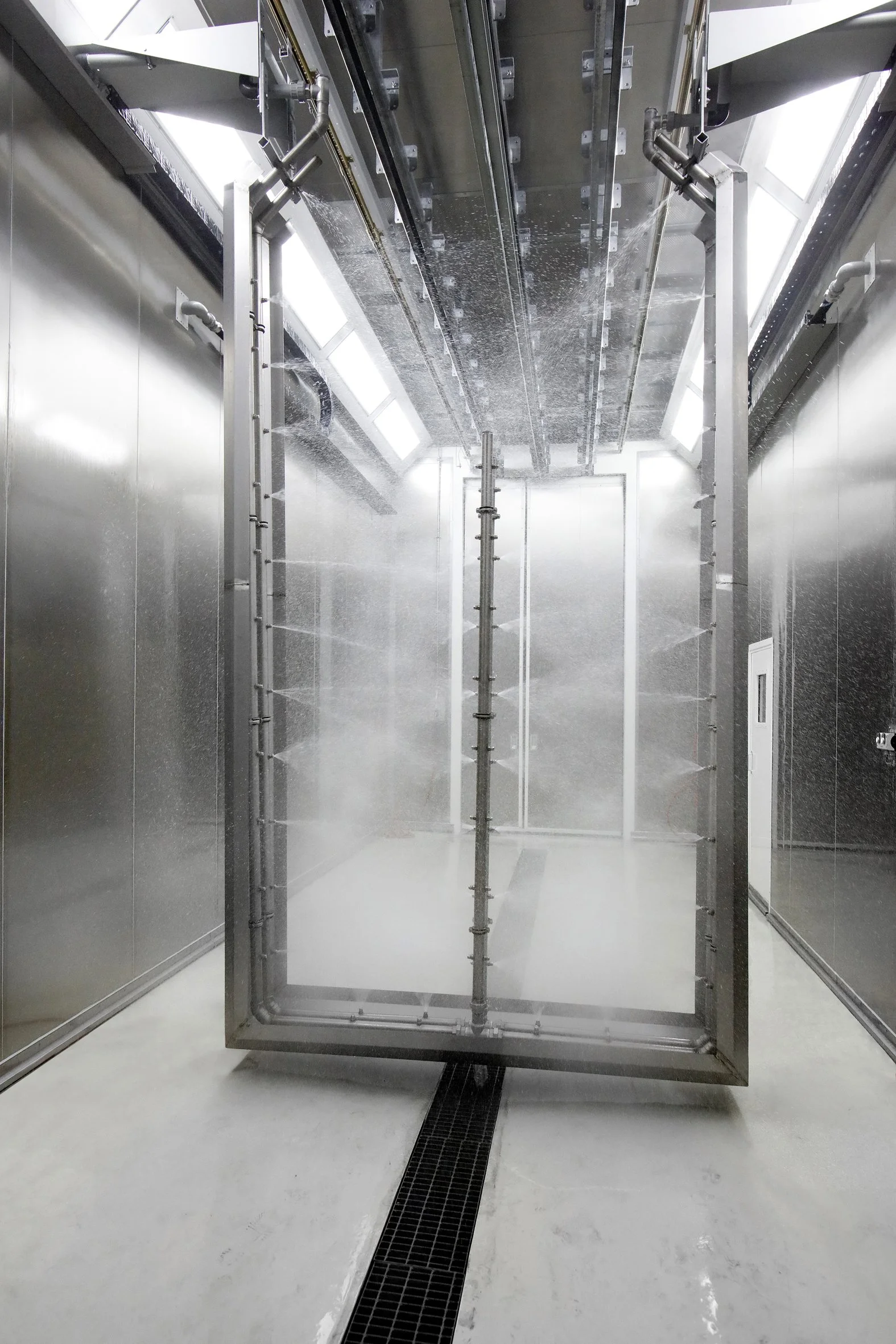
![Transfer Carriage H100 Pre-treatment]()
Transfer Carriage H100 Pre-treatment
-
![Transfer Carriage HT]()
Transfer Carriage HT